ASTM D395 Method A Rubber Property Compression Set


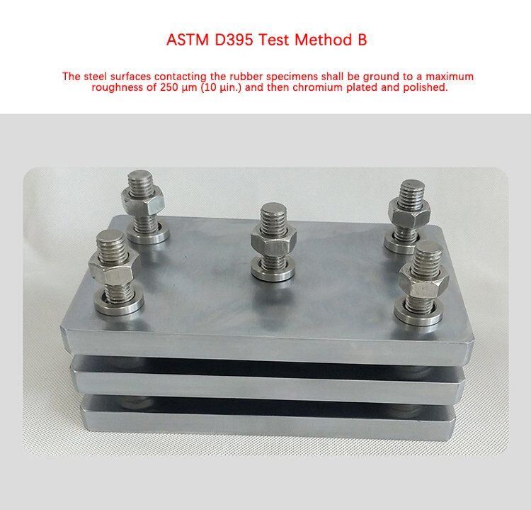
ASTM D395 Method B Rubber Property Compression Set


1. Scope ASTM D395 Rubber Properties Compression Permanent Deformation:
These test methods cover the testing of rubber intended for use in applications in which the rubber will be subjected to compressive stresses in air or liquid media. They are applicable particularly to the rubber used in machinery mountings, vibration dampers, and seals. Two test methods are covered as follows:
2. ASTM D395 Test Method:
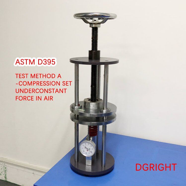
Method A-Compression Set Under Constant Force in Air
Method B-Compression Set Under Constant Deflection in Air
- The choice of test method is optional, but consideration should be given to the nature of the service for which correlation of test results may be sought. Test Method B shall be used unless otherwise stated in a detailed specification.
- Test Method B is not suitable for vulcanizates harder than 90 IRHD.

3. ASTM D395 Test Specimens:
| Size | 1A | 2B |
| Thickness, mm(in) | 12.5±0.5 | 6.0±0.2 |
| (0.49±0.02) | (0.24±0.01) | |
| Diameter, mm(in) | 29.0±0.5 | 13.0±0.2 |
| (1.14±0.02) | (0.51±0.01) |
A Type 1 specimen is used in Test Methods A and B.
B Type 2 specimen is used in Test Method B.
4. ASTM D395 Method A Test Procedure:
(TEST METHOD A-COMPRESSION SET UNDER CONSTANT FORCE IN AIR)

4.1 Conditioning – Prepare specimens
4.1.1 Store all vulcanized test specimens or product samples to be tested at least 24 hours but not more than 60 days. When the date of vulcanization is unknown, tests should be performed within 60 days after delivery by the producer of the article represented by the specimen.
4.1.2 Allow buffed specimens to rest for at least 30 min before specimens are cut for testing.
4.1.3 Condition all specimens before testing for a minimum of 3 h at 23 ± 2°C(73.4 ± 3.6°F). Specimens whose compression set properties are affected by atmospheric moisture shall be conditioned for a minimum of 24 h in an atmosphere controlled to 50±5% relative humidity.
4.2 Test Procedure
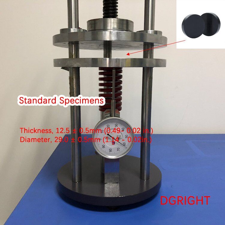
4.2.1 Original Thickness Measurement: Measure the original thickness of the specimen to the nearest 0.02 mm (0,001 in.). Place the specimen on the anvil of the dial micrometer so that the presser foot will indicate the thickness at the central portion of the top and bottom faces.

Fig. 1
4.2.2 Application of Compressive Force: Assemble the specimens in the compression device, using extreme care to place them exactly in the center between the plates to avoid tilting. If the calibrated spring device (see Fig. 1) is used, apply the compressive force by tightening the screw until the deflection as read from the scale is equivalent to that shown on the calibration curve for the spring corresponding to a force of 1.8 kN (400 lbf). With the external loading device (see Fig. 2), apply this force to the assembly in the compression machine or by adding required masses, but in the latter case, take care to add the mass gradually without shock. Tighten the nuts and bolts just suficiently to hold the initial defections of the specimen and spring. It is imperative that no additional force be applied in tightening the bolts.

4.2.3 Test Time and Test Temperature: Choose a suitable temperature and time for the compression set, depending upon the conditions of the expected service. In comparative tests, use identical temperature and heating periods. It is suggested that the test temperature be chosen from those listed in Practice D1349. Suggested test periods are 22 h and 70 h. The specimen shall be at room temperature when inserted into the compression device. Place the assembled compression device in the oven within 2 h after completion of the assembly and allow it to remain there for the required test period in dry air at the test temperature selected; at the end of the test period, take the device from the oven and remove the specimens immediately and allow it to cool.
4.2.4 Cooling Period: While cooling, allow the specimens to rest on a poor thermally conducting surface, such as wood, for 30 min before making the measurement of the final thickness. Conduct the cooling period at a standard laboratory temperature of 23 ±2°C(73.4 ± 3.6°F). Specimens whose compression set property is affected by atmospheric moisture shall be cooled in an atmosphere controlled to 50±5% relative humidity.
4.2.5 Final Thickness Measurement: After the rest period, measure the final thickness at the center of the specimen per 2.4.

4.3 Calculation
Calculate the compression set as a percentage of the original thickness as follows:
CA=[(t0-ti)/t0]x100
Where:
CA= Compression set (Test Method A) as a percentage of the original thickness,
t0=original thickness (see 4.2.1), and
ti=final thickness(see 4.2.5).
4.4 Report
Report the following information:
4.4.1 Original dimensions of the test specimen, including the original thickness, t0.
4.4.2 Actual compressive force on the specimen as determined from the calibration curve of the spring and spring deflection reading or as applied by an external force.
4.4.3 Thickness of the test specimen 30 min after removal from the clamp, ti;
4.4.4 Type of test specimen used, together with the time and temperature of the test.
4.4.5 Compression set, expressed as a percentage of the original thickness.
4.4.6 Test method used (Test Method A), and
4.4.7 Number of specimens tested.
5. ASTM D395 Method B Test Procedure:
(TEST METHOD B-COMPRESSION SET UNDER CONSTANT DEFLECTION IN AIR)

5.1 Test Procedure
5.1.1 Original Thickness Measurement: Measure the original thickness of the specimen to the nearest 0.02 mm (0.001 in.). Place the specimen on the anvil of the dial micrometer so that the presser foot will indicate the thickness at the central portion of the top and bottom faces.
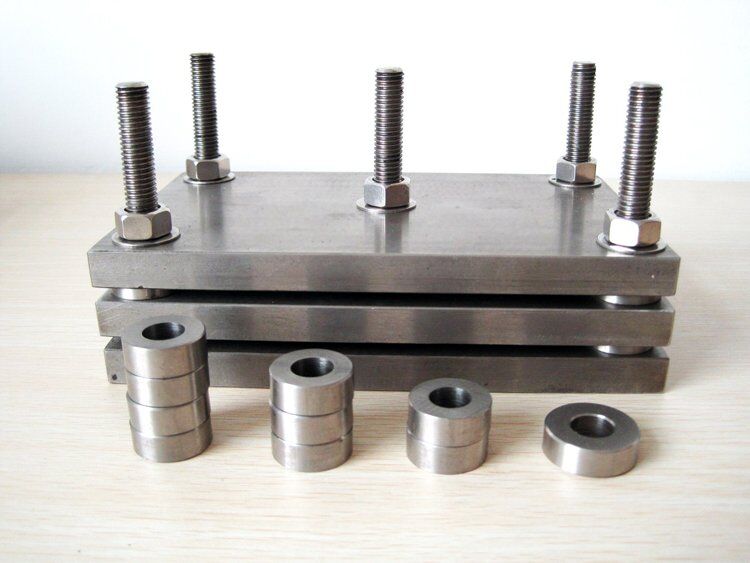
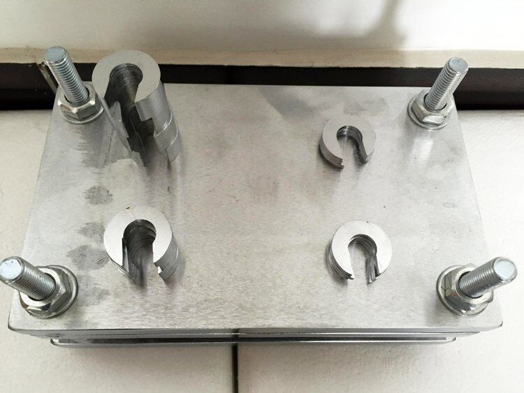
5.1.2 Application of Compressive Force: Place the test specimen between the plates of the compression device with the spacers on each side, allowing sufficient clearance for the bulging of the rubber when compressed (see Fig. 3). Where a lubricant is applied, it shall consist of a thin coating of a lubricant having substantially no action on the rubber. For most purposes, a silicon or fluorosilicon fluid is suitable. Tighten the bolts so that the plates are drawn together uniformly until they are in contact with the spacers. The amount of compression employed shall be approximately 25 %. A suitable mechanical or hydraulic device may be used to facilitate assembling and disassembling the test fixture.

5.1.3 Test Time and Temperature: Choose a suitable temperature and time for the compression set, depending upon the conditions of the expected service. In comparative tests, use identical temperature and test periods. It is suggested that the test temperature be chosen from those listed in Practice D 1349. Suggested test periods are 22 h and 70 h. The test specimen shall be at room temperature when inserted in the compression device. Place the assembled compression device in the oven within 2 h after completion of the assembly and allow it to remain there for the required test period in dry air at the test temperature selected. At the end of the test period, take the device from the oven and remove the test specimen immediately and allow them to cool.
5.1.4 Cooling Period: While cooling, allow the test specimen to rest on a poor thermally conducting surface, such as wood, for 30 min before making the measurement of the final thickness. Maintain the conditions during the cooling period in accordance with 4.2.4.
5.1.5 Final Thickness Measurement: After the rest period, measure the final thickness at the center of the test specimen in accordance with 5.1.1.

5.2 Calculation
Calculate the compression set as a percentage of the original thickness as follows:
CB=[(t0-ti)/(t0-tn)]x100
where:
CB= compression set (Test Method B) expressed as percentage of the original deflection
t0= original thickness of specimen (13.1)
ti= final thickness of specimen (13.5), and
tn= thickness of the spacer bar used.
5.3 Report
Report the following information:
5.3.1 Original dimensions of the test specimen including the original thickness, t0,
5.3.2 Percentage compression of the specimen actually employed,
5.3.3 Thickness of the test specimen 30 min after removal from the clamp, ti,
5.3.4 Type of test specimen used, together with the time and temperature of test.
5.3.5 Whether or not the surfaces of the compression device are lubricated. If they are, what type lubrication was used.
5.3.6 Compression set, expressed as a percentage of the original deflection.
5.3.7 Test method used (Test Method B), and
5.3.7 Number of specimens tested.
ISO 815 Rubber vulcanized or thermoplastic-Determination of compression set

1. Scope ISO 815 Rubber Properties Compression Permanent Deformation:
This document specifies methods for the determination of the compression set characteristics of vulcanized and thermoplastic rubbers at ambient one method) or elevated temperatures three methods, A, B, and C, depending on the way the test piece is released at the end of the test).
The methods are intended to measure the ability of rubbers of hardness within the range 10 IRHD to 95 IRHD to retain their elastic properties at specified temperatures after prolonged compression at constant strain (normally 25 % under one of the alternative sets of conditions described, For rubber of nominal hardness 80 IRHD and above, a lower compression strain is used: 15 % for a nominal hardness from 80 IRHD to 89 IRHD and 10 % for a nominal hardness from 90 IRHD to 95 IRHD.
NOTE 1: When rubber is held under compression, physical or chemical changes that prevent the rubber from returning to its original dimensions after release of the deforming force can occur. The result is a set, the magnitude of which depends on the time and temperature of compression and the time, temperature, and conditions of recovery. At elevated temperatures, chemical changes become increasingly more important and lead to a permanent set.
NOTE 2: Short-time compression set tests, typically for 24 h, at elevated temperatures are commonly used as a measure of the state of cure, a means of material classification, and a specification to ensure the quality of a compound. Longer tests, typically for 1,000 h, at elevated temperatures take account of the effect of aging and are often used to predict service performance, including that of sealing materials. Short-time tests at ambient temperature show mainly the effect of physical changes (re-orientation of the molecular chains and the fillers).
2. ISO 815 Test Apparatus
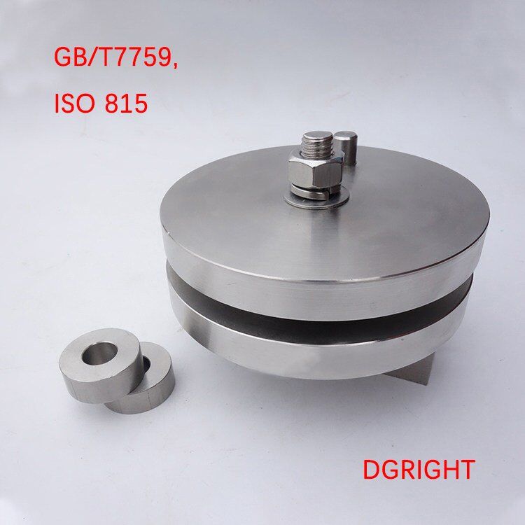
2.1 Compression assembly, consisting of compression plates, steel spacers, and clamping device.
A typical assembly is shown in Figure 1.

2.2 Compression plates, consisting of two parallel, flat, highly polished plates made of chromium-plated steel or stainless-steel or any corrosion-resistant material between the faces of which the testpiece is compressed.

2.3 Steel spacer(s), to provide the required compression.
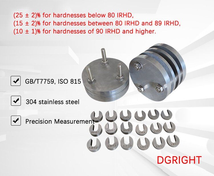
The spacer(s) shall be of such size and shape that contact with the compressed test piece is avoided. The height of the spacer(s) shall be chosen so that the compression applied to the test piece is:
(25 ± 2)% for hardnesses below 80 IRHD,
(15 ± 2)% for hardnesses between 80 IRHD and 89 IRHD,
(10 ± 1)% for hardnesses of 90 IRHD and higher.
2.4 Clamping device, a simple screw device (see Figure 1) is adequate.
2.5 Oven, in accordance with the requirements specified in IS0 188:2011, method A or method B.

RT-306 Laboratory High-Temperature Electric Drying Oven
2.6 Pair of tongs, for handling the test pieces.
2.7 Thickness gauge, with an accuracy of ±0,01 mm (see IS0 23529:2016, 9.1), having a flat circular foot of 4,0 mm ± 0,5 mm in diameter and a flat solid base-plate and exerting a pressure of 22 kPa ± 5 kPa for solid rubber of hardness equal to or greater than 35 IRHD, or a pressure of 10 kPa ± 2 kPa if the hardness is less than 35 IRHD.
2.8 Timing device, for measuring the recovery time, with an accuracy of ±1 s.
3. ISO 815 Test Pieces
3.1 Dimensions
The test pieces shall be one of two sizes, designated type A and type B.
Type A: a cylindrical disc of diameter 29,0 mm ± 0,5 mm and thickness 12,5 mm ± 0,5 mm
Type B: a cylindrical disc of diameter 13,0 mm ± 0,5 mm and thickness 6,3 mm ± 0,3 mm.
Table A.1 -Type 1 precision for compression set at 100 °C:
| Material | Average | Within lab | Between lab | ||
| r | (r) | R | (R) | ||
| Type A test piece | |||||
| EPDM | 10,3 | 2,7 | 26 | 4,0 | 38 |
| NBR | 19,8 | 3,3 | 17 | 4,3 | 21 |
| SBR | 41,1 | 4,7 | 11 | 13,6 | 33 |
| Pooled values | 23,7 | 3,6 | 15 | 8,6 | 36 |
| Type B test piece | |||||
| EPDM | 14,8 | 3,3 | 22 | 4,5 | 30 |
| NBR | 24,4 | 4,3 | 18 | 7,7 | 32 |
| SBR | 44,9 | 5,1 | 11 | 14,0 | 33 |
| Pooled values | 28,0 | 6,0 | 15 | 10,0 | 35 |
Table A.2 -Type 1 precision for compression set at 23 °C (Type A)
| Material | Units | Percent | |||||
| Mean level | sr | r | (r) | sR | R | (R) | |
| EPDM | 7,5 | 0,85 | 2,39 | 31,9 | 0,85 | 2,39 | 31,9 |
| IIR | 5,4 | 0,50 | 1,42 | 26,1 | 0,86 | 2,44 | 45,0 |
| SBR | 8,4 | 1,26 | 3,56 | 42,3 | 2,25 | 6,38 | 75,8 |
| Average | 7,1 |
| |||||
| Pooled values | 0,92 | 2,61 | 36,7 | 1,48 | 4,18 | 58,7 | |
| NOTE: Preferred precision in bold | |||||||
Table A.3 -Type 1 precision for compression set at 100 °C (Type A)
| Material | Units | Percent | |||||
| Mean level | sr | r | (r) | sR | R | (R) | |
| EPDM | 27,2 | 1,12 | 3,16 | 11,6 | 2,39 | 6,75 | 24,8 |
| IIR | 58,6 | 1,26 | 3,56 | 6,1 | 2,40 | 6,78 | 11,6 |
| SBR | 32,8 | 1,32 | 3,74 | 11,4 | 1,69 | 4,78 | 14,6 |
| Average | 39,5 | ||||||
| Pooled values | 1,24 | 3,50 | 8,9 | 2,18 | 6,18 | 15,6 | |
| NOTE: Preferred precision in bold | |||||||
Table A.4-Type 1 precision for compression set at 23 °C (Type B)
| Material | Units | Percent |
| ||||
| Mean level | sr | r | (r) | sR | R | (R) | |
| EPDM | 5,4 | 0,43 | 1,23 | 22,7 | 0,88 | 2,48 | 46,0 |
| IIR | 3,6 | 0,53 | 1,49 | 41,1 | 0,93 | 2,64 | 73,0 |
| SBR | 7,2 | 0,50 | 1,42 | 19,6 | 0,69 | 1,94 | 26,9 |
| Average | 5,4 | ||||||
| Pooled values | 0,49 | 1,48 | 25,5 | 0,84 | 2,37 | 43,9 | |
| NOTE: Preferred precision in bold | |||||||
Table A.5 -Type 1 precision for compression set at 100 °C (Type B)
| Material | Units | Percent | |||||
| Mean level | sr | r | (r) | sR | R | (R) | |
| EPDM | 27,0 | 0,87 | 2,45 | 9,1 | 1,22 | 3,47 | 12,8 |
| IIR | 58,8 | 0,43 | 1,23 | 2,1 | 2,58 | 7,31 | 12,4 |
| SBR | 37,4 | 1,69 | 4,78 | 12,8 | 1,69 | 4,78 | 12,8 |
| Average | 41,1 | ||||||
| Pooled values | 1,12 | 3,18 | 7,7 | 1,92 | 5,42 | 13,2 | |
| NOTE: Preferred precision in bold | |||||||

RIGHT's Services Always Go Extra Mile
No more endlessly wasting time on other lousy suppliers. RIGHT's goal is to let you sit back and relax. We take care of all the dirty works, including trade stuff, clearance and logistics, etc. Our consultant will keep you informed of the trade progress throughout.
Related products
-

Automatic Opening and Closing Rubber Dispersion Kneader (RT-123)
-

RT-133 Rubber Compression Heat Generation Flexometer Testing Machine (ASTM-D623)
-

RT-110A Button Type Two Roll Mill (Adjustable Speed Ratio)
-

Plastic Hot Press Forming and Rubber Vulcanizing Press Machine Manufacturers
-

RT-118 Rubber Trimming Machine
-

RT-112 Rubber Hose Friction Tester
-

RT-108B Rubber Rebound Resilience Impact Tester
-

Rubber Moving Die Rheometer MDR Rotorless Curemeter Price (RT-101)
